This is the first post of many documenting my drone project. This is the largest project I have ever undertaken and it is meant to hone my skills in many different technologies and aspects of software, hardware, and control theory. As such, it will comprise multiple sub-projects and span a number of months. This post will state the high level goals of the project and its various components.
Goals
In one sentence, the point of this project is to create a drone from scratch which can fly autonomously. To be more specific, the primary goal is for the drone to maintain level flight and accept commands to translate or rotate in space. Additional autonomy could then be built upon this foundation. This requires deep knowledge in a number of engineering fields, primarily in software, hardware, and control theory.
The technical goals of the project are detailed in the Components section below. In addition, there are a few overarching goals I would like to highlight:
- Application of C++17 (in both application software and embedded software)
- Hardware control and design as necessary
- Graphics programming for viewing/simulating the drone
- Robotics controls engineering in general
Components
This section breaks down the subcomponents of the project. One or multiple posts will dive into the details of each section in the future.
The Drone Itself
First and foremost, the physical drone. I have decided to build the drone from scratch at a subsystem level. To be more precise, I purchased and assembled the macro components of a drone, i.e. the flight controller, the motors, the frame, etc. Since the main point of this project is not hardware design, most of these boards were bought commercially. That being said, I did have a need for some custom hardware so I designed and manufactured the drone’s wireless communication board.
As for the software, I initially flashed the flight controller with an open source drone firmware. This allowed me to check that the hardware worked correctly, by flying the drone manually with a handheld radio transmitter. The final firmware, currently under development, is written from scratch in C++17. This custom firmware utilizes FreeRTOS as a real-time operating system to manage task scheduling.
The firmware’s duties include consuming and processing sensor data, deriving the state of the drone from this sensor data, running this state through an on-board control algorithm, and commanding the drone’s motors accordingly. It will also downlink data in real-time through a telemetry system, which is detailed below.
Telemetry Pipeline
The autonomous drone firmware itself, while the focal point of the project, is just one component. Various infrastructure is also being developed to support the drone. One part of that infrastructure is a telemetry pipeline which provides insight into the drone’s state in real-time.
The pipeline is architected as follows:
- On every control loop cycle, the drone flight controller gathers data from sensors and sends it to an on-board telemetry transmitter
- The drone’s telemetry transmitter downlinks this data to a telemetry receiver (PCB connected to a computer via USB)
- The telemetry receiver then forwards the data to a desktop viewing application
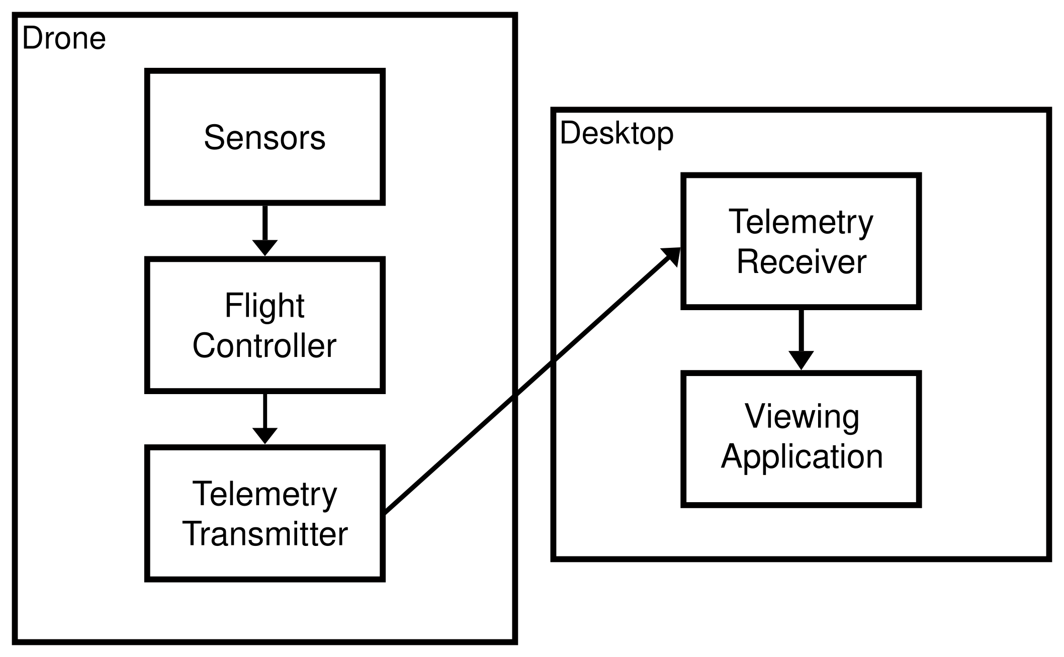
The “viewing application” mentioned above renders a model of the drone in a 3D environment which allows for a visual inspection of the drone’s state. This allows the user to easily check the drone’s sensor readings and derived state.
Control Theory
To get the drone flying autonomously, a few control theory concepts must be implemented. First, the drone must determine its “state”. That is, the drone must determine its own position and orientation in space. This will be accomplished with a Kalman filter, which is a sensor fusion algorithm capable of deriving the state of a system from various sensor readings.
Before a Kalman filter can be employed, an accurate dynamic model must be created for the system. This allows us to construct the matrices used in the Kalman filter computations.
Lastly, a stable controller must be developed to ensure our system stays at a given set point (i.e. position and orientation). This may be possible to develop either theoretically (with the aforementioned dynamic model) or experimentally (with a simulator, as discussed below). PID controllers are quite popular and straightforward to implement, but a different controller could also be used.
Tuning and Testing
While testing a design and tweaking it to work just perfectly is challenging with any engineering system, it is especially challenging when the system is an airborne one with the potential to cause damage. Because of this, thought must be put into safely testing the system from the very beginning.
As a first step, simulating the drone is helpful for a number of reasons. First, it allows quick iteration of the PID controller without having to set up the drone, clear a space for the drone to fly, charge a battery, etc. Second, it is much safer to test the initial controller in a simulated environment where the drone cannot cause any physical harm or damage.
Once the simulator is built, the PID controller can be tuned fairly easily. The next step is an iterative process to see how well a tuned controller maps from the simulated drone to the physical drone. This essentially tests the fidelity of the dynamic model: If the controller maps well, then the model is accurate enough. Else, additional complexity must be added to the model. Additional sensors may also be added if finding a stable controller algorithm proves impossible.
When testing the physical drone, additional safety precautions will be put in place. First, the drone will be tethered to the ground to prevent problems if its flight becomes too erratic. Second, a remote on/off switch has been developed to instantly turn the drone off if necessary. Third, the tests themselves will start very simple and get more complex as the system is refined. For example, the very first test will be a hover test starting in the air. The second test will be translating up and down in space. Tests will then advance in complexity from there, progressing to rotating, translating horizontally, etc.
Commanding
The final step of the project is to create a method for controlling the drone. While it must be able to maintain level flight autonomously, it must also accept basic position/orientation commands. For example, it could be commanded to translate vertically/horizontally and rotate about all three axes. A desktop application will be developed to send these inputs to the drone. This application has not been designed yet, but it may be bundled into the viewing application mentioned earlier.
Conclusion
This project is quite large, and intentionally so. It is essentially developing a fully automated robotics system from the ground up, in a way that lets me experience each facet of the process. Through this I will develop a better understanding of the design process as a whole, from the perspectives of software, control theory, hardware, etc. Stay tuned for more posts about this project!